
Magnet drive side channel pump (barrel design)
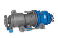 This chemical resistant, self-priming, extremely safe pump is further proof of our product expertise.
These pumps are mainly used in situations where, by law, discharge must be realized "overhead". The configuration of the SLM SV allows the gas flow to be transported along with the fluid. The pump can also achieve low NPSH values if an upstream centrifugal stage is realized.
Series
Following is a partial listing of the very extensive combination options:
SLM SVS
Design features
- Process oriented design
- Self-priming
- Barrel design
- 1-8 stages
- Only 2 static seals
- Magnet drive
- Leakproof
- Horizontally mounted
- Modular system
- Greased ball bearing
Technical data
Q up to 35 m3/h with 50Hz / up to 41 m3/h with 60Hz
H up to 310 m with 50Hz / up to 445 m with 60Hz
t from -40 °C up to +250 °C
p up to PN 40
Special constructions up to PN400
Higher outputs available.
Materials
Standard construction
Casing elements: 316 SS
Impeller/paddle wheels: 316 SS
Isolation shell: 316 Ti/Hastelloy C4
Magnet carrier: 316 Ti
Internal bearings: silicon carbide
Bearing lantern: nodular iron
Bearing carrier: ductile iron
Other materials available
SLM SVB H12W
Design features
- Process oriented design
- Self-priming
- Barrel design
- 1-8 stages
- Only 2 static seals
- Magnet drive
- Leakproof
- Horizontally mounted
- Modular system
- Jacketed bearing lantern
- Heated pump casing
- Heating connection
- Thermal barrier
- Secondary seal
- Close coupled configuration
Technical data
Q up to 35 m3/h with 50Hz / up to 41m3/h with 60Hz
H up to 310 m with 50Hz / up to 445 m with 60Hz
t from -40 °C up to +250 °C
p up to PN 40
Special constructions up to PN400
Higher outputs available.
Materials
Standard construction
Casing elements: 316 SS
Impeller/paddle wheels: 316 SS
Isolation shell: 316 Ti/Hastelloy C4
Magnet carrier: 316 Ti
Internal bearings: silicon carbide
Bearing lantern: nodular iron
Other materials available
Identification code:
Bearing carrier realizations:
| Bearing carrier | Realization | Comments |
| SLM SVS | Standard | Greased, with deep groove ball bearing |
| SLM SVO | Standard | Oiled, with deep groove ball bearing |
Close-coupled realization:
| Variants | Realization | Comments |
| SLM SVB | Close coupled configuration | Motor carrier (without shaft coupling |
Suffixes (designs):
| H5 | heated pump casing |
| H2 | jacketed bearing lantern |
| S | thermal barrier without secondary seal |
| W | thermal barrier with secondary seal |
| Z, C | isolation shell made of zirconium oxide (Z); isolation shell with CFK plastic cladding (C) |
| D | double isolation shell |
Design variants
Heated pump H5 and/or H2
The pumps are outfitted with a heat jacket and pump casing (H5) and/or a heat jacket in the bearing lantern (H2). Both heat jackets can be realized either separately or in conjunction with a bypass line. The heat jackets in the standard construction are rated for operating pressure of 16 bar at 200 ?°C (steam) or 6 bar at 350 ?°C. The heat jackets can also be used for cooling.
S or W thermal barrier and secondary seal
The thermal barrier acts as a structural element between the bearing carrier (in the bearing carrier model) or drive motor (in the close coupled model), whereas the hydraulic system allows for heat transfer. This reduces ball bearing temperatures in the gearing when hot liquids are being transported. A radial shaft sealing ring can also be integrated into the thermal barrier for purposes of sealing the magnet driver. The sealing ring acts as a secondary seal that prevents the product from leaking into the environment through a leak in the isolation shell. In order for this secondary seal to be used, the magnet driver chamber must be monitored so that leaks can be detected in good time.
Double isolation shell D
The double isolation shell should be used in situations requiring a high level of safety. The unit consists of two interlocking isolation shells, both of which are rated for the relevant operating conditions. If one of the two units is damaged, the casing still remains leaktight. The gap between the two units can be monitored.